


In optical communication networks, appropriate path planning can improve the utilization of communication resources and bring a smooth communication experience to users. The following figure shows an inter-satellite optical communication network. User messages are sent from one terrestrial base station (nodes $$$4$$$ to $$$7$$$) and transmitted through satellites (nodes $$$0$$$ to $$$3$$$) in space to another terrestrial base station (nodes $$$4$$$ to $$$7$$$).
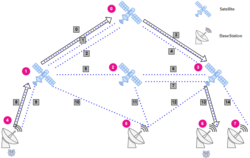
In the preceding figures, there are communication connections (edges for short) between base stations and satellites and between satellites. The base stations and satellites are referred to as nodes.
User messages are transmitted on these edges and referred to as flows. Some users may make video calls with friends, and some users may send short messages to their family members. Therefore, the message traffic (called flow rate) of each user differs.
There are many parallel edges (for example, edges $$$0$$$, $$$1$$$, and $$$2$$$) between two nodes, and the capacity of each edge also differs. Larger capacity indicates that more user messages can be transmitted, as well as shorter transmission distance indicates lower latency and better communication quality.
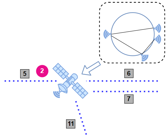
Nodes also have their internal structure. As shown below, some edges inside a node cannot communicate with each other because these edges (constrained edge pair) are not fully connected. For example, edge $$$5$$$ and edge $$$7$$$ inside node $$$2$$$ cannot communicate with each other, and therefore flows cannot pass through node $$$2$$$ by traversing the two unconnected edges.
Now, in the input network, the source node, target node, and required flow rate for each user flow are specified. Because network resources are limited, paths may not be successfully calculated for all user flows. We hope that you can provide a solution with the highest score.
Note, that
- all edges are undirected, so flows may come in both directions,
- edges has both capacity and length (named distance),
- several flows may use the same edge,
- flows may come through the same edge in opposite directions simultaneously,
- for the purpose of this problem, there is no difference between satellites and base stations, so flows may come through several base stations before reaching the destination station.
Constraints
- The capacity of each edge is limited. The total rate of all flows carried by an edge cannot exceed the capacity of the edge. The capacity limits the total flows in both directions.
- The calculated flow path does not allow loops or cycles.
- Due to the hardware limitation inside satellites, the number of flows passing through a node (including source and target node) cannot exceed the site flow limit ($$$\mathit{SFL}$$$) of the node. The value of $$$\mathit{SFL}$$$ is $$$200$$$.
- There are multiple parallel edges between two nodes, which may belong to different groups. Links in each group are managed by the same chip on a node, and there is a group flow limit ($$$\mathit{GFL}$$$). The total number of different flows on all the edges in a group cannot exceed the $$$\mathit{GFL}$$$ of the group. The value of $$$\mathit{GFL}$$$ is $$$100$$$.
- By default, all edges are connected to each other in each node. But there are some constrained edge pairs — the pairs of edges inside specified nodes that cannot communicate with each other.
- You can make no more than $$$2$$$ submissions on each $$$5$$$ minutes interval.
The first line contains four integers separated by space: $$$\mathit{NodeCount}$$$, $$$\mathit{EdgeCount}$$$, $$$\mathit{ConstrainedCount}$$$, and $$$\mathit{FlowCount}$$$.
- $$$8 \le \mathit{NodeCount} \le 1400$$$,
- $$$15 \le \mathit{EdgeCount} \le 15000$$$,
- $$$3 \le \mathit{ConstrainedCount} \le 3600$$$,
- $$$1 \le \mathit{FlowCount} \le 14000$$$.
The next $$$\mathit{EdgeCount}$$$ lines contain information about the network. Each line contains six integers: $$$\mathit{EdgeID}$$$, $$$\mathit{GroupID}$$$, $$$\mathit{StartNodeID}$$$, $$$\mathit{EndNodeID}$$$, $$$\mathit{Distance}$$$, and $$$\mathit{Capacity}$$$.
- $$$0 \le \mathit{EdgeID} < \mathit{EdgeCount}$$$,
- $$$0 \le \mathit{GroupID} \le 4500$$$,
- $$$0 \le \mathit{StartNodeID}, \mathit{EndNodeID} < \mathit{NodeCount}$$$,
- $$$\mathit{StartNodeID} \ne \mathit{EndNodeID}$$$,
- $$$100 \le \mathit{Distance} \le 10000$$$,
- $$$1 < \mathit{Capacity} \le 10^5$$$.
It's guaranteed that only multiple edges may share the same $$$\mathit{GroupID}$$$.
The next $$$\mathit{ConstrainedCount}$$$ lines contain information about the edge pairs that are not connected in the specified nodes of the network. All other edges are connected to each other by default. Each line contains three integers: $$$\mathit{NodeID}$$$, $$$\mathit{EdgeID}_1$$$, and $$$\mathit{EdgeID}_2$$$.
- $$$0 \le \mathit{NodeID} < \mathit{NodeCount}$$$,
- $$$0 \le \mathit{EdgeID}_1, \mathit{EdgeID}_2 < \mathit{EdgeCount}$$$,
- $$$\mathit{EdgeID}_1 \ne \mathit{EdgeID}_2$$$.
The next $$$\mathit{FlowCount}$$$ lines contain information about the flows to be calculated. Each line contains four integers: $$$\mathit{FlowID}$$$, $$$\mathit{SourceNode}$$$, $$$\mathit{TargetNode}$$$, and $$$\mathit{FlowRate}$$$.
- $$$0 \le \mathit{FlowID} < \mathit{FlowCount}$$$,
- $$$0 \le \mathit{SourceNode}, \mathit{TargetNode} < \mathit{NodeCount}$$$,
- $$$\mathit{SourceNode} \ne \mathit{TargetNode}$$$,
- $$$2 \le \mathit{FlowRate} \le 12000$$$
Don't forget that the $$$\mathit{SFL}$$$ and $$$\mathit{GFL}$$$ mentioned above are also important parameters.
For the simplicity, both $$$\mathit{EdgeID}$$$ and $$$\mathit{FlowID}$$$ of the $$$i$$$-th ($$$0$$$-indexed) edge (flow) is always equal to $$$i$$$.
In the first line, output the number of your success flows.
Next, each line output edge information about the path that a flow passes through.
The format is as follows: $$$\mathit{FlowID}\ \mathit{EdgeID}_1\ \mathit{EdgeID}_2\ \mathit{EdgeID}_3\ \dots\ \mathit{EdgeID}_n$$$.
There is no requirement on the output sequence between flow paths, but edges in one flow must be outputted in order, from source node to target node. Please output all successfully calculated flow paths. For other flows that are not output, the checker determines that you have not found appropriate paths for the flows by default.
- The solutions that violate constraints, time out, or exceed the memory limit are invalid.
- According to the formula $$$\mathit{Score}=\mathit{SuccessFlowNum}+\max \left(1-\left(\frac{\mathit{AvgDistance}}{1000000}\right),0\right)$$$, the solution with a higher score wins. (That is, the solution with more successfully planned flow paths wins. If two solutions have the same number of successfully planned flow paths, the solution with a smaller average of path distances wins. Output with $$$0$$$ flow paths will be considered incorrect.)
- If two solutions have the same score, the solution submitted first wins.
- For multiple tests, the ranking is performed based on the sum of all tests. If the solution has no result on any test, it will be recorded as no result on the whole.
- Among your multiple submissions, the one with the highest score is the final score.
- The checker runs your solution on exactly one CPU core, so multithreading implementation will not provide any profit.
- You can make no more than $$$2$$$ submissions on each $$$5$$$ minutes interval.
8 15 3 1
0 0 0 1 100 1050
1 1 0 1 200 2200
2 1 0 1 200 99400
3 2 0 3 100 450
4 3 0 3 500 1120
5 4 1 2 1000 40000
6 5 2 3 600 10000
7 5 2 3 600 10000
8 6 1 4 120 2500
9 6 1 4 120 450
10 7 1 5 170 1250
11 8 2 5 200 2500
12 9 3 5 100 1250
13 10 3 6 300 1150
14 11 3 7 300 1100
2 5 7
2 6 7
2 6 11
0 4 6 100
1
0 8 0 3 13
The total distance of a flow path is $$$620$$$ ($$$120 + 100 + 100 + 300 = 620$$$). (Note: 0 9 10 12 13 is also a valid output result.)
